Hydraulic Cylinder Basic Knowledge
Oct 11, 2023Hydraulic oil is pressed into the hydraulic cylinder will produce a lot of pressure, this pressure has been applied to many mechanical equipment, especially in the field of IC and electric forklift is widely used!
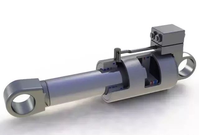
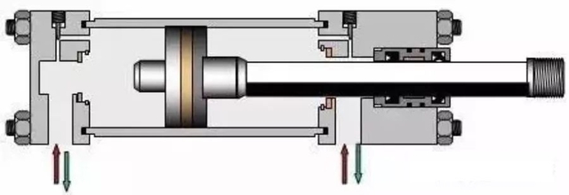
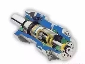
Hydraulic cylinder is a hydraulic actuator that converts hydraulic energy into mechanical energy and does linear reciprocating movement (or swinging movement). It is simple in structure and reliable in operation. When it is used to achieve reciprocating movement, the deceleration device can be eliminated, and there is no transmission gap, and the movement is smooth, so it is widely used in various mechanical hydraulic systems.
The output force of the hydraulic cylinder is proportional to the effective area of the piston and the pressure difference between the two sides; The hydraulic cylinder is basically composed of cylinder and cylinder head, piston and piston rod, sealing device, buffer device and exhaust device. Buffer device and exhaust device depending on the specific application, other devices are essential.
Composition of hydraulic cylinder
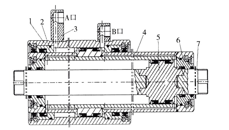
Cylinder: The cylinder is the main part of the hydraulic cylinder, which forms a closed chamber with the cylinder head, piston and other parts to promote the piston movement.
Cylinder head: The cylinder head is installed at both ends of the hydraulic cylinder and forms a tight oil chamber with the cylinder. There are usually welding, thread, bolt, clamp and tie rod and other connection methods, generally according to the working pressure, the connection of the cylinder, the use of the environment and other factors to choose.
Piston rod: Piston rod is the main component of hydraulic cylinder transmission force. The material is generally selected as medium carbon steel (such as 45 steel). When the cylinder is working, the piston rod is subject to thrust, tension or bending torque, etc., and it is necessary to ensure its strength; And the piston rod often slides in the guide sleeve, and the fit should be appropriate.
Piston: It is the main component that converts hydraulic energy into mechanical energy, and its effective working area directly affects the force and movement speed of the hydraulic cylinder. Piston and piston rod connection has a variety of forms, commonly used with the ring type, shaft sleeve type and nut type.
Guide sleeve: guide sleeve plays a guiding and supporting role on the piston rod, which requires high precision, low friction resistance, good wear resistance, and can withstand the pressure, bending force and impact vibration of the piston rod. The inside is equipped with a sealing device to ensure that the cylinder is sealed by the rod cavity, and the outside is equipped with a dust ring to prevent impurities, dust and moisture from being brought to the sealing device and damaging the seal.
Buffer device: the piston and piston rod have great momentum when they are driven by liquid pressure, and when they enter the end cover of the cylinder and the bottom of the cylinder, they will cause mechanical collision, resulting in great impact pressure and noise. The buffer device is used to avoid such collisions. The working principle is that the oil (in whole or in part) in the low pressure chamber of the cylinder is converted into heat energy by throttling, and the heat energy is brought to the hydraulic cylinder by the circulating oil. The structure of the buffer device is divided into two types: constant throttling area buffer device and variable throttling buffer device.
Principle of hydraulic transmission
With the oil as the working medium, the movement is transmitted through the change of the sealing volume, and the power is transmitted through the pressure inside the oil. Power part: Convert the mechanical energy of the prime mover into the pressure energy of the oil (hydraulic energy). For example: hydraulic pump.
Execution part: The hydraulic pump input oil pressure energy into the mechanical energy to drive the working mechanism. For example: hydraulic cylinder, hydraulic motor.
Control part: used to control and adjust the pressure, flow and flow direction of the oil. For example: pressure control valve, flow control valve and direction control valve.
Auxiliary part: the first three parts are connected together to form a system, which plays the role of oil storage, filtration, measurement and sealing. Examples include pipes and joints, fuel tanks, filters, accumulators, seals and control instruments.
Main parameters of hydraulic cylinder
The main parameters of the hydraulic cylinder include pressure, flow, size, piston stroke, movement speed, pushing force, efficiency and hydraulic cylinder power.
Pressure: Pressure is the pressure of the oil on a unit area. The formula p=F/A is the load acting on the piston divided by the effective working area of the piston. On the effective working area of the same piston, the greater the load, the greater the pressure required to overcome the load.
Flow rate: Flow rate is the volume of effective cross-sectional area of oil passing through cylinder in unit time. Calculation formula Q=V/t=vA, where V represents the volume of oil consumed by the hydraulic cylinder piston in one stroke, t represents the time required by the hydraulic cylinder piston in one stroke, v represents the piston rod movement speed, and A represents the effective working area of the piston.
Piston stroke: Piston stroke refers to the distance traveled between the poles when the piston moves back and forth. Generally, after meeting the stability requirements of the cylinder, the standard stroke similar to it is selected according to the actual working stroke.
Piston speed: The speed of movement is the distance that the pressure oil pushes the piston to move in unit time, which can be expressed as v=Q/A. Size specifications: The size specifications mainly include the inner and outer diameter of the cylinder, the diameter of the piston, the diameter of the piston rod and the size of the cylinder, etc. These dimensions are calculated, designed and checked according to the use environment of the hydraulic cylinder, the installation form, the push force required to provide and the stroke.
Hydraulic cylinder internal design
Design purpose: According to the site working temperature, working medium and factory processing conditions. According to the mechanical design manual, calculate the size of the internal structure.
1. The selection of sealing must be selected according to the on-site working temperature, environmental pollution and working medium. Water-glycol media cannot be sealed with polyurethane.
2. The cylinder head of the cylinder is sealed with V-type combination as far as possible, which can make up for the error of the finish of the groove processing.
3. The size of the sealing groove is designed in strict accordance with the design manual.
4. The cylinder piston seal is generally made of Glace ring plus guide belt, which has good high temperature resistance and pollution resistance.
5. The cylinder seal is generally used in Japan NOK series, and must not use domestic cylinder seals, otherwise the cylinder starting resistance is too large, the action is not smooth or even does not work.
6. The O-ring between the cylinder head and the cylinder is sealed, and it is best to add a stop ring, so as to make up for the processing error.
7. The connection of cylinder and cylinder head bottom and middle swing should not be welded as far as possible, because welding will cause cylinder deformation, and can be threaded connection or other connection methods.
Hydraulic cylinder common problems and maintenance
Hydraulic cylinder leakage
External leakage refers to the oil leakage from the seal is not strict to the atmosphere outside the hydraulic cylinder, the most common external leakage has the following three places
(1) Oil leakage in the sealing part of the hydraulic cylinder liner and the cylinder head (or guide sleeve) (solution: replace the new O-ring);
(2) The piston rod and the guide sleeve relative movement of the oil leakage (solution: if the piston rod is damaged, it can be cleaned with gasoline, after drying, apply metal glue to the damage, and then use the piston rod oil seal to move back and forth on the piston rod to scratch the excess glue, such as the glue is completely cured before being put into use. If the guide sleeve is worn, it can be replaced with a guide sleeve with a slightly smaller inner diameter); (3) Oil leakage caused by the weak seal of the hydraulic cylinder pipe joint (Solution: in addition to checking the sealing of the seal ring, it should also check whether the joint is correctly assembled, whether it is reliably tightened and whether the contact surface has scars, etc., replace or repair if necessary)
Internal leakage refers to the leakage of oil from the high pressure chamber to the low pressure chamber through various gaps in the hydraulic cylinder. Internal leakage is more difficult to detect, and can only be judged by system operating conditions, such as insufficient thrust, reduced speed, unstable operation, or high oil temperature rise. Hydraulic cylinder leakage generally has the following two places:
(1) The static sealing part between the piston rod and the piston (solution: install O-rings on the sealing surface of the two);
(2) The dynamic sealing part between the inner wall of the cylinder liner and the piston (Solution: When internal leakage is found, the mating parts should be strictly inspected first. The repair of cylinder liner mostly adopts the method of boring the inner hole, and then it is equipped with a large diameter piston)
Add:No.609 Tahui Road , Shihudang Town, Songjiang District ,Shanghai, China


Friendly Links :
© 2026 Shanghai Zon-Cho Huge Science And Technology Co., Ltd. All Rights Reserved.
|Sitemap|Xml |Privacy Policy